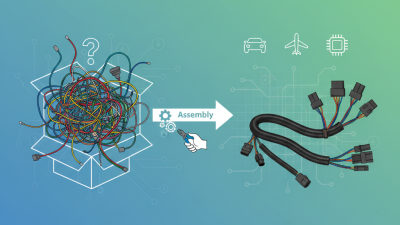
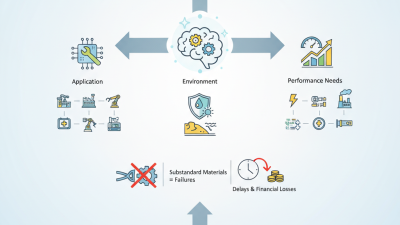
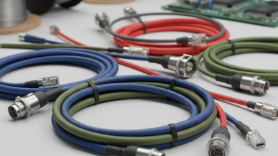
Choosing bespoke cable assemblies in 2026 requires more than comparing unit prices. It demands evidence, engineering judgment, and careful supplier evaluation. MarketsandMarkets’ Cable Assemblies Market report identifies continued growth, driven by electric vehicles, aerospace systems, medical equipment, and industrial automation. Grand View Research also reports sustained expansion across the broader wire and cable sector. These trends increase demand for smaller, faster, and more traceable assemblies.
Performance begins with the application. Define voltage, current, signal frequency, temperature, flex cycles, and installation space. Then examine conductor size, shielding, insulation, connector plating, and bend radius. A cable may look suitable on a drawing but fail beside a motor, in a sterilization chamber, or inside a vibrating vehicle. Eric Bogatin, a respected signal-integrity educator, states, “A transmission line is a transmission line.” That reminder matters when selecting high-speed bespoke cable assemblies, especially where impedance and crosstalk affect system reliability.
The strongest suppliers support design reviews, first-article inspection, continuity testing, hipot testing, and documented traceability. IPC/WHMA-A-620 remains a key workmanship reference for cable and wire harness assemblies. Ask for material certificates and test records, not attractive promises. No checklist is perfect. Real installations expose assumptions. A connector that works on a clean workbench may loosen after thousands of flex cycles. Therefore, the right choice balances customization, standards compliance, production capacity, and field experience. Review every tolerance twice. Small omissions can become expensive failures in 2026.
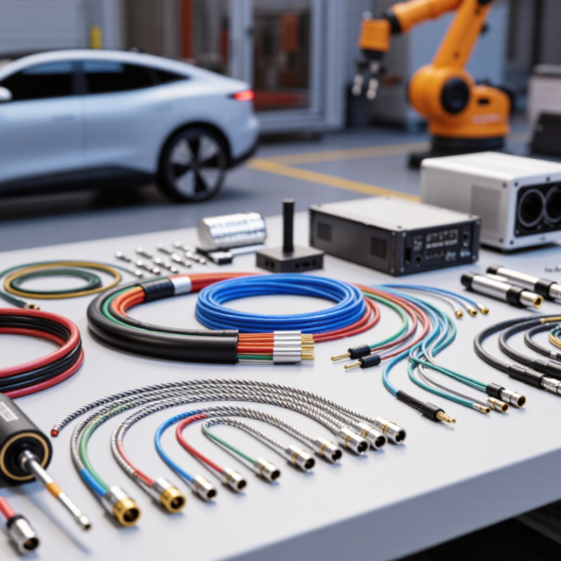
How to Choose Bespoke Cable Assemblies in 2026
Define Requirements for a Bespoke Cable Assembly
A reliable bespoke cable assembly starts with a clear, measurable requirement. Record the operating voltage, current, signal type, cable length, and acceptable tolerance. State whether the assembly carries power, data, or both. Measure the real installation route. Do not rely only on an old drawing. Measure it twice.
Describe the working environment in practical terms. Include temperature ranges, moisture exposure, vibration, chemical contact, and repeated movement. Specify the minimum bend radius and available space around the cable. Connector details also matter. Define contact material, locking method, keying, and required ingress protection. A small mismatch can stop an entire installation.
Keep the specification easy to verify. Request conductor size, insulation material, shielding method, and jacket construction. Define tests for continuity, insulation resistance, polarity, and pull strength. Ask for inspection records and traceable drawings. These details support consistent quality and safer maintenance.
Avoid vague phrases such as “heavy duty” or “standard length.” They invite different interpretations. In practical assembly work, unclear requirements often create expensive rework. I have seen a connector fit mechanically but fail during vibration testing. That mistake was preventable. A short checklist helps, although it will never replace technical review. Recheck every assumption before production.
| Requirement Area | What to Define | Electrical Rating | Nominal voltage, operating current, peak current, signal type, and allowable voltage drop. | 24 V DC power circuit; continuous current of 8 A; short-duration peak current of 12 A; maximum voltage drop of 3%. | Determines conductor cross-sectional area, insulation system, contact rating, and the need for separate power and signal circuits. | Continuity test, resistance measurement, voltage-drop calculation, and dielectric withstand testing where applicable. | |
|---|---|---|---|---|---|---|---|
| Conductor Selection | Conductor material, cross-sectional area, strand construction, flexibility, and conductor class. | Copper conductors with a defined cross-sectional area; flexible stranded construction for repeated movement; conductor classification documented to IEC 60228 where applicable. | Affects current-carrying capacity, flexibility, fatigue life, resistance, termination method, and assembly cost. | Review conductor datasheets, measure conductor resistance, and inspect cross-section or construction records. | |||
| Cable Length and Geometry | Finished length, tolerance, branch locations, connector orientation, bend direction, and routing envelope. | Finished length of 1,500 mm with a specified production tolerance; two branches positioned from a defined datum; connectors keyed in a defined orientation. | Controls fit, installation time, strain distribution, serviceability, and the risk of forced bending or connector misalignment. | Use a controlled drawing, dimensional inspection, a full-size routing fixture, and first-article approval. | |||
| Bend and Flexing | Minimum static bend radius, dynamic bend radius, flexing cycles, travel distance, speed, and acceleration. | Continuous-flex application requiring 1,000,000 motion cycles; bend radius to be taken from the selected cable construction and validated by testing rather than assumed as a universal value. | Influences conductor stranding, insulation, shielding, jacket material, lay length, strain relief, and cable-chain suitability. | Perform a representative flex test using the actual routing radius, speed, load, and cycle count. | |||
| Environmental Conditions | Operating and storage temperature, humidity, water exposure, chemicals, oil, dust, UV radiation, vibration, and shock. | Operating range of −20 °C to +80 °C; occasional water exposure; exposure to vibration; no unverified chemical-resistance assumption. | Determines jacket and insulation materials, sealing method, protective sleeving, connector sealing, and mechanical retention. | Compare material ratings with the application profile and conduct thermal, vibration, ingress, or chemical tests as required. | |||
| Ingress Protection | Required protection against solid objects and water at the installed interface or enclosure boundary. | IP65 for protection against dust ingress and water jets when the complete mated interface is designed and tested for that level under IEC 60529. | Requires compatible sealing gaskets, backshells, cable glands, plugs, and controlled assembly processes. | Test the complete mated assembly, including cable exits and unused positions, according to the specified IP level. | |||
| Signal Integrity and EMC | Signal frequency, data rate, impedance, attenuation, crosstalk, shielding, grounding, and separation from power conductors. | Differential data pair with a controlled nominal impedance defined by the system interface; shield termination method specified at one or both ends according to the EMC design. | Affects pair geometry, twist, shielding construction, connector choice, pin assignment, and routing separation. | Check pinout and continuity; measure impedance or insertion loss when required; perform EMC testing at system level. | |||
| Connector and Pinout | Interface type, contact quantity, keying, gender, mating cycles, contact plating, latch style, and pin assignment. | A keyed multi-contact connector with defined mating orientation; unused contacts identified; pinout controlled by a released wiring schedule. | Determines compatibility, assembly tooling, serviceability, contact reliability, and prevention of incorrect mating. | Verify connector part specifications, perform pin-to-pin testing, inspect keying, and complete a mating/unmating check. | |||
| Mechanical Protection | Abrasion, tensile load, crush risk, pull-out force, strain relief, bend protection, and mounting method. | A defined maximum installation pull force; molded or clamped strain relief at each termination; abrasion protection required at a chassis pass-through. | Influences overmolding, backshells, conduit, braided sleeving, grommets, clamps, and jacket selection. | Conduct pull, flex, abrasion, retention, and visual inspection tests using production-representative samples. | |||
| Safety and Compliance | Applicable electrical, flammability, wiring, environmental, and product-specific regulatory requirements. | Document the applicable equipment standard, required flammability classification, restricted-substance requirements, and traceability obligations before design release. | May limit material choices, construction methods, labeling, documentation, and manufacturing controls. | Maintain a compliance matrix, material declarations, inspection records, and required qualification reports. | |||
| Manufacturing and Quality | Crimp method, stripping dimensions, soldering or ultrasonic welding requirements, inspection criteria, test coverage, and revision control. | Every finished assembly receives 100% continuity and short-circuit testing; crimp dimensions and pull-force criteria are defined in the production specification. | Improves repeatability, reduces intermittent faults, and supports reliable production scaling and field traceability. | Use controlled work instructions, calibrated tooling, crimp inspection, electrical test records, and lot traceability. | |||
| Identification and Documentation | Cable identification, wire numbering, connector labels, drawings, bill of materials, test records, and revision status. | Permanent cable ID at both ends; released drawing showing dimensions and pinout; controlled revision code recorded on inspection documents. | Simplifies installation, troubleshooting, maintenance, repeat ordering, and configuration management. | Perform document review, label legibility inspection, and comparison against the approved drawing and wiring schedule. |
All example values should be confirmed against the actual equipment, installation environment, applicable standards, and complete cable-assembly test plan before production release.