Choosing an Electronic Power Transformer begins with the job it must perform, not the size of its enclosure. The term can describe different transformer designs, so confirm the intended application and operating principle before comparing products. A lighting supply, control cabinet, and industrial converter may need very different electrical characteristics.
Write down the input voltage, output voltage, frequency, and required power in watts or volt-amperes. Include the load’s normal operating pattern, startup current, and any sensitive electronics connected downstream. These details matter. A transformer that matches the nominal voltage may still struggle with brief inrush peaks or continuous heat.
Next, check isolation requirements, efficiency, insulation class, cooling method, and expected temperature rise. Consider where the unit will operate: a sealed cabinet, a dusty workshop, or a warm equipment room each presents different demands. Review the manufacturer’s datasheet for ratings, connection diagrams, protection features, and stated test conditions. If the application involves unusual harmonics, tight voltage tolerances, or limited ventilation, ask the manufacturer or a qualified electrical engineer to review the selection.
Price and compact dimensions can be tempting, but they do not tell the whole story. Compare the complete specifications against the real load and installation conditions. A little uncertainty is normal; product labels are not always consistent. Verify unclear terms before ordering, and confirm that the chosen model can be installed and maintained safely.
Begin with the load, not the transformer rating. List every connected device, its voltage, phase, frequency, and rated power. Then estimate which equipment will run at the same time. A motor may draw several times its normal current during startup; pumps, compressors, and lifts can therefore create brief but demanding peaks. Check the manufacturer’s inrush-current data, expected duty cycle, and any planned future loads. Small details matter.
The U.S. Department of Energy’s 2016 technical analysis estimated that distribution transformers account for about 2.5% of U.S. electricity consumption. That figure makes operating efficiency worth considering alongside capacity. Compare no-load losses, which occur whenever the transformer is energized, with load losses, which rise as demand increases. For a site with steady, round-the-clock demand, these costs may carry more weight than they do for intermittent equipment.
Verify the supply voltage and available fault current with a qualified electrical professional, then confirm that the proposed transformer meets applicable IEC 60076 requirements. Do not size from total connected load alone. I have seen neat load lists miss startup surges and future additions; real operating conditions are rarely quite so tidy.
Choosing the transformer type starts with the load and installation environment. Dry-type units suit indoor spaces where containing liquid is a concern; liquid-immersed units are common outdoors and in higher-capacity applications. Isolation transformers provide electrical separation, while autotransformers can be smaller when input and output voltages are close. Match the choice to the actual duty, cooling, enclosure, and maintenance access—not just the purchase price.
Size the unit in kilovolt-amperes (kVA), using the load’s apparent power rather than watts alone. Check continuous demand, starting current, future expansion, ambient temperature, and nonlinear loads that may create harmonics. A motor that draws 30 kVA while running may demand much more briefly at startup. Avoid excessive oversizing: a lightly loaded transformer still has core losses.
The U.S. Department of Energy’s 2013 distribution-transformer standards analysis estimated that these transformers used about 2.5% of U.S. electricity, underscoring the value of efficient selection and operation. Confirm the estimate and efficiency class against the applicable DOE analysis and current equipment data.
Tips: Record peak load over time, then compare it with the nameplate rating and manufacturer derating guidance. Include voltage, phase, frequency, and impedance in the specification. A tidy spreadsheet can still miss a short startup surge; check field measurements where possible.
How to Choose an Electronic Power Transformer?
Check Voltage, Frequency, and Regulation Specifications
Choosing an electronic power transformer starts with matching the input voltage to the actual supply. A label marked 120 volts may not suit a line that regularly rises to 127 volts. Measure the outlet with a reliable meter during different operating periods. Small variations can affect sensitive control boards and communication circuits.
Frequency matters too. Confirm whether the transformer supports 50 Hz, 60 Hz, or both. A mismatched frequency can increase heating, vibration, or unwanted noise. In practical installations, I have seen equipment perform normally during testing but become hot after several hours. That result was easy to miss. Ambient temperature and ventilation deserve attention.
Regulation specifications show how steadily the output voltage remains under load. A transformer with poor regulation may provide the correct voltage without a connected device, then drop noticeably during operation. Compare no-load and full-load output values. Check the tolerance stated in the technical sheet, not only the nominal rating. Also review the rated power, startup demand, insulation class, and protection requirements. I once treated a short voltage test as sufficient, and that judgment was incomplete. A longer test with the real load would have exposed the weakness. Use qualified measuring equipment and record readings before approving the installation.
| Selection Dimension | What to Check | Typical Specification or Range | Why It Matters | Selection Guidance |
|---|---|---|---|---|
| Input Voltage | Nominal supply voltage and allowable variation | For example, 120 V AC or 230 V AC; confirm the permitted input range, such as ±10% | The transformer primary winding must match the available supply to prevent overheating, poor output voltage, or insulation stress. | Choose a primary rating that matches the actual system voltage, not only the nominal label. |
| Output Voltage | Required secondary voltage at the intended load | Common low-voltage outputs include 5 V, 9 V, 12 V, 15 V, 18 V, 24 V, and 48 V AC | The output voltage determines whether downstream rectifiers, control circuits, sensors, or actuators operate correctly. | Allow for voltage drop under load and verify whether the required value is AC or DC after rectification. |
| Voltage Ratio | Relationship between primary and secondary windings | Approximately proportional to the turns ratio: Vp/Vs ≈ Np/Ns | The ratio establishes the basic step-up or step-down function of the transformer. | Use the rated ratio together with the specified load condition because winding losses affect the actual output voltage. |
| Frequency | Frequency of the AC supply | 50 Hz or 60 Hz; some designs are rated for both | Frequency affects core flux, magnetizing current, losses, noise, and thermal performance. | Do not operate a transformer designed only for 60 Hz at 50 Hz unless the manufacturer confirms compatibility. |
| Rated Power | Required apparent power in volt-amperes | Typical control and electronic transformers range from approximately 10 VA to several hundred VA | The VA rating indicates how much combined voltage and current the transformer can supply continuously without exceeding its temperature limit. | Calculate VA as V × A for the AC load, then select a practical margin of about 20–30% for continuous operation and inrush. |
| Secondary Current | Continuous current required by the load | Secondary current ≈ rated VA ÷ secondary voltage | Insufficient current capacity can cause overheating, excessive voltage sag, and premature insulation aging. | Check both the continuous current and any short-duration startup or inrush current. |
| Voltage Regulation | Change in secondary voltage from no load to rated load | Typical small power transformers may have approximately 5–15% regulation, depending on design and rating | Higher regulation percentage means a larger output-voltage change as the load varies. | For sensitive electronics, choose a low-regulation design or add suitable regulation after rectification. |
| Efficiency | Ratio of output power to input power | Often approximately 80–95% for small units; larger properly loaded units may achieve higher values | Efficiency affects energy consumption, heat generation, enclosure temperature, and operating cost. | Compare efficiency at the expected operating load rather than relying only on the maximum published value. |
| Insulation Class | Thermal endurance of the insulation system | Common thermal classes include Class A: 105°C, Class B: 130°C, Class F: 155°C, and Class H: 180°C | A higher thermal class can provide greater temperature capability when used within the complete design limits. | Select the class according to ambient temperature, enclosure conditions, duty cycle, and required service life. |
| Isolation | Electrical separation between primary and secondary circuits | Use an isolation transformer when galvanic separation is required; verify dielectric withstand and insulation ratings | Isolation can improve safety and help reduce the transfer of certain common-mode disturbances. | Confirm creepage, clearance, dielectric strength, and protective-earth requirements for the intended installation. |
| Load Type | Nature of the connected load | Resistive, capacitive, inductive, rectifier-input, motor, solenoid, or switching power supply | Loads with capacitors, motors, or magnetic components may draw high startup current and create waveform distortion. | Increase the VA margin or select a transformer specifically rated for inrush-sensitive loads. |
| Ambient Temperature | Temperature surrounding the transformer during operation | Common reference conditions are around 25°C or 40°C; derating may be required above the rated ambient temperature | Higher ambient temperature reduces the available thermal margin and can shorten insulation life. | Check the temperature-rise rating and apply the specified derating for enclosed or high-temperature locations. |
| Mounting and Cooling | Enclosure size, ventilation, orientation, and mounting method | Open-frame, chassis-mount, PCB-mount, enclosed, or encapsulated construction | Restricted airflow can raise winding and core temperatures even when the electrical load is within the VA rating. | Provide adequate clearance and ventilation, and avoid placing heat-sensitive components directly beside the transformer. |
| No-Load Current | Primary current drawn with the secondary unloaded | Should remain within the design specification; it depends on core material, frequency, voltage, and construction | Excessive no-load current may indicate unsuitable frequency, overvoltage, saturation, or abnormal losses. | Review this value when standby consumption, heat, or energy efficiency is important. |
| Safety Protection | Fuse, circuit breaker, thermal protection, and short-circuit behavior | Primary overcurrent protection sized according to the transformer rating and applicable electrical code | Protection limits fault energy and helps prevent fire, winding damage, and unsafe temperatures. | Use the recommended fuse type and rating, considering inrush current and the installation category. |
| Compliance Requirements | Applicable product and installation standards | Requirements may include national electrical codes, safety standards, EMC rules, and environmental restrictions | Compliance supports safe installation, reliable operation, and acceptance in the target market. | Verify the required approvals for the end product and country before finalizing the transformer. |
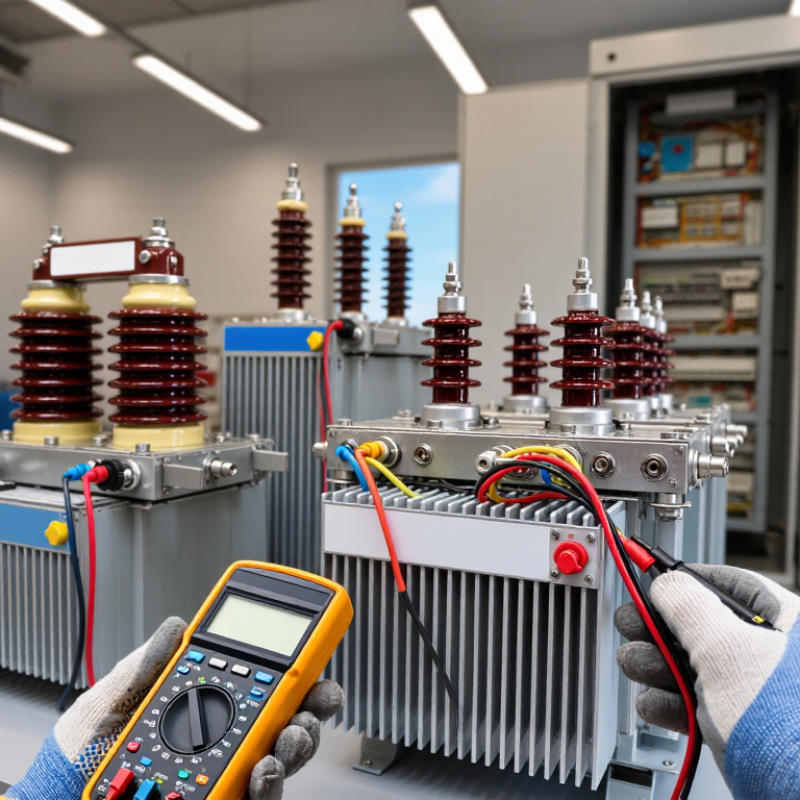
How to Choose an Electronic Power Transformer?
Efficiency is not only a catalog percentage. It affects heat, operating cost, and service life. The U.S. Department of Energy estimated that distribution transformers consume 60–80 billion kWh annually. That makes small efficiency differences financially meaningful. Compare no-load and load losses at your actual duty cycle. A transformer running at 30% load needs different priorities than one operating near capacity.
Protection must match the installation, not just the voltage rating. Check overload behavior, short-circuit withstand, thermal monitoring, surge protection, grounding, and enclosure requirements. The IEC 60076 series provides widely used testing and performance guidance. Also examine ambient temperature, altitude, humidity, dust, and ventilation. Harmonic-rich loads can create additional heating. The IEA’s Electricity Grids and Secure Energy Transitions report shows that grid losses remain significant, often around 8% in advanced economies and higher in developing systems. A poorly selected transformer adds avoidable loss.
Tips: Request test data at several loading points. Confirm protection settings with a qualified engineer. A spreadsheet can still mislead. Real loads are rarely balanced. Review one week of measured demand when possible, including startup peaks and nighttime operation. I would also question optimistic assumptions about cooling. A quiet cabinet may still be running hot inside. Leave practical thermal margin, but avoid oversizing blindly, because very low loading can increase the importance of no-load losses.
How to Choose an Electronic Power Transformer?
Confirm compatibility before comparing prices or enclosure styles. Check the input voltage, output voltage, frequency, phase, and required power rating. A transformer rated at 500 VA may overheat when a motor creates a heavy startup surge. Leave a practical margin, often 20–30%, but verify the equipment manual first. Also inspect the load type. Sensitive control circuits and resistive heaters do not behave the same way.
Installation details matter. Choose a dry, ventilated location with enough space around the enclosure. Do not place the unit beside steam pipes or dusty grinding equipment. Mount it securely, keep cables short where possible, and separate power wiring from signal wiring. Grounding must follow local electrical codes and the manufacturer’s instructions. I would not assume a familiar wiring layout is safe. Small terminal errors can produce dangerous voltage. A qualified electrician should check the final connections.
Tips: Confirm the transformer’s insulation class, temperature rating, short-circuit protection, and enclosure rating. Look for test documentation that matches recognized standards, such as IEC 61558 or applicable regional requirements. Requirements can differ between countries, and online listings are sometimes incomplete. Record the measured input and output voltage after installation. Recheck them under normal load. It is a simple step, but it is often skipped.
Confirm that the transformer's rated input frequency matches the available supply. The chart compares ideal 230 V RMS sine-wave references at 50 Hz and 60 Hz. Before installation, also verify input and output voltage, load power, enclosure conditions, grounding, wiring clearances, and applicable safety requirements such as IEC 61558 where relevant.
The peak value is approximately 325 V for a 230 V RMS sine wave. Use the transformer's datasheet to confirm frequency, voltage tolerance, rated power, insulation class, protection rating, and permitted installation environment.