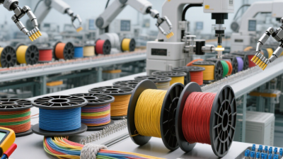
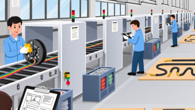
Wire harness assembly is the organized connection system behind power, data, and control in modern equipment. It combines wires, terminals, connectors, seals, clips, labels, and protective sleeving. The final structure depends on electrical load, installation space, vibration, temperature, and service requirements.
Industry data shows why these assemblies deserve closer attention. MarketsandMarkets reported that the global wire harness market could grow from about USD 93.1 billion in 2023 to USD 112.6 billion by 2028. Its analysis links this growth to vehicle electrification, factory automation, and expanding electronic content. Grand View Research also identifies automotive electrification and advanced vehicle systems as major growth factors. However, market definitions differ between reports. Some include cable assemblies, while others focus only on harness products. That inconsistency matters.
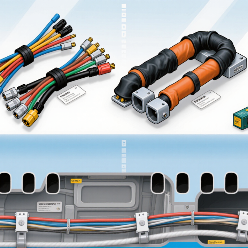
The top types of wire harness assembly usually include point-to-point harnesses, custom equipment harnesses, automotive harnesses, industrial control harnesses, medical harnesses, and aerospace harnesses. Each type solves a different physical problem. A vehicle harness may require abrasion protection beside a hot engine. A medical harness may prioritize clean routing and traceable materials. An industrial harness may need flexible movement across a robotic axis. Aerospace designs demand strict weight, documentation, and inspection controls.
There is no universal “best” harness. A lower-cost design can increase repair time later. A highly protected harness can become unnecessarily heavy. Engineers commonly use IPC/WHMA-A-620 for workmanship guidance, but project specifications still require careful review. This article compares the leading harness types, their construction details, common applications, and selection considerations. The goal is practical clarity, not a perfect classification.
What Are the Top Types of Wire Harness Assembly?
Point-to-point harnesses connect individual wires between defined terminals, connectors, sensors, or control devices. Their quality depends on accurate routing, secure terminations, and clear documentation. IPC/WHMA-A-620 acceptance Classes 1–3 provide different quality expectations for these assemblies. Class 1 suits general electronic products where basic function is the main concern. Class 2 requires consistent workmanship for products needing reliable service and longer operating life. Class 3 applies to high-performance environments where failure may create serious operational risks.
Inspection should match the selected class. Technicians typically check conductor stripping, crimp height, solder flow, insulation support, connector locking, and circuit continuity. A pull test may confirm mechanical strength when required by the work instructions. Labels must remain readable, and wire routing should avoid sharp bends, pinching, heat, and unwanted tension. Small details matter. A misplaced seal can allow movement or moisture entry.
The acceptance class should come from the product’s use, risk level, and customer documentation. A higher class is not automatically better for every harness. It may increase inspection time and manufacturing cost without improving a simple application. Visual appearance can also mislead; a neat harness may hide a weak crimp. No inspection plan is perfect. Reviewing recurring defects, measuring process capability, and updating instructions can expose weaknesses that a final check misses.
| Acceptance class | General product category | Typical point-to-point harness context | Inspection emphasis | Acceptance approach |
|---|---|---|---|---|
| Class 1 | General Electronic Products | Harnesses for products where the primary requirement is basic function and the consequences of failure are relatively low. | Verify that the assembly is complete, correctly connected, and meets the applicable workmanship requirements for items such as conductors, terminations, insulation, and identification. | Use the Class 1 criteria specified by the applicable standard revision and procurement documents. The assembly must meet the defined requirements for its intended use. |
| Class 2 | Dedicated Service Electronic Products | Harnesses for products where continued performance and extended service life are important, but uninterrupted operation is not typically essential. | Apply the specified criteria to connection integrity, routing and support, protection from damage, and workmanship at terminations and splices. | Use the Class 2 requirements agreed for the product. These requirements are generally more demanding than Class 1 where the standard identifies class-dependent acceptance criteria. |
| Class 3 | High Performance Electronic Products | Harnesses for products where continued performance is critical and equipment downtime may not be acceptable. | Closely evaluate workmanship and conformance to specified assembly details, including electrical connections, insulation condition, conductor support, and protection against mechanical or environmental damage. | Use the Class 3 criteria specified for the product and applicable standard revision. Class selection should reflect the end-use requirements and documented risk. |
Note: IPC/WHMA-A-620 provides acceptance criteria for cable and wire harness assemblies; it does not by itself define the harness design or product requirements. The applicable revision, class, drawings, and contract documents determine the specific acceptance criteria. “Point-to-point” describes connections between designated endpoints and is not itself an acceptance class.

Automotive wire harnesses carry power and signals through hot, vibrating spaces, from engine bays to door panels. ISO 6722-1 and SAE J-1128 describe cable requirements, but they should not be treated as interchangeable labels. ISO 6722-1 covers single-core road-vehicle cables in defined voltage and temperature categories. SAE J-1128 addresses low-voltage primary cable. Check the applicable edition and cable specification before choosing conductors.
Voltage class is only one part of a sound harness design. Confirm the circuit’s operating and transient voltages, then match insulation, conductor size, and temperature rating to the installation. A cable routed near an engine may face heat and abrasion that a cabin circuit does not. Review terminal compatibility and routing too; a correctly rated cable can still fail when pinched against a sharp bracket. The details matter.
Tips: Read the cable marking and verify it against the drawing and test documentation. Keep records of standard editions and temperature classes. If a specification is unclear, pause and confirm it with the responsible engineer. Small labeling gaps can create real confusion later.
Industrial power harnesses remain one of the most demanding wire harness types. They distribute energy through motors, cabinets, pumps, drives, and battery systems. UL 758 AWM ratings can reach 600 V, but the voltage rating alone does not approve an entire assembly. Conductor size, insulation temperature, spacing, abrasion resistance, and bend radius must match the application.
The International Energy Agency’s Electricity 2024 report forecasts global electricity demand growth of about 4% annually through 2026. More power equipment means more dense wiring, tighter enclosures, and greater heat exposure. In production, I check routing around sharp metal edges, then verify strain relief at every termination. Small details matter. A neat drawing can still hide a weak bend radius.
Control harnesses usually carry lower power and more signal separation. Sensor and communication harnesses require stronger noise control and careful shielding. Industrial power harnesses need both electrical capacity and mechanical discipline. IPC/WHMA-A-620 guidance supports consistent workmanship for crimping, routing, labeling, and inspection. However, a standard cannot replace testing. I prefer voltage, continuity, insulation, pull-force, and thermal checks before release. The imperfect part is often documentation; field changes are easy to miss. A 600 V AWM marking should be treated as one verified design condition, not a shortcut around engineering review.
Coaxial and shielded harnesses control signal integrity where ordinary wire bundles cannot. A 50 Ω harness is common in radio-frequency, wireless, and test equipment circuits. A 75 Ω harness suits video, broadcast, and high-frequency monitoring systems. The impedance must remain consistent from connector to connector. Small mismatch, big trouble.
A 2024 industry forecast report on the global coaxial cable market identifies wireless infrastructure, vehicle electronics, and data centers as major demand areas. These applications expose weak harness designs quickly. A 50 Ω cable connected to a poorly matched termination can increase reflections and insertion loss. For 75 Ω video paths, even a small impedance discontinuity may create ghosting or unstable high-speed signals. I have seen failures caused by a connector crimp that looked acceptable but changed the contact geometry. Visual inspection missed it.
Shielding controls electromagnetic interference, not just physical damage. Braided shields provide flexibility, while foil shields offer more continuous high-frequency coverage. The correct choice depends on frequency, bending, grounding, and connector design. IEC 61196-1 emphasizes controlled electrical performance across coaxial cable assemblies, including impedance and attenuation requirements. EMC testing should examine the complete harness, not the cable alone. The enclosure, drain wire, backshell, and grounding path all matter. Sometimes, over-shielding creates a grounding mistake. That deserves review.
The chart compares the magnitude of signal reflection caused by common load impedances. Reflection coefficient magnitude is calculated as |(ZL − Z0) / (ZL + Z0)|. Correct impedance matching minimizes reflections, while the cable shield helps control electromagnetic interference.
Reference conditions: ideal transmission-line calculation at the indicated nominal impedance; actual harness performance also depends on connector quality, shielding construction, grounding, routing, and frequency.
A 28 VDC harness can look simple on a drawing. In the aircraft, it must handle current, vibration, heat, and tight routing.
SAE AS50881 provides aircraft wire-installation practices, while FAA AC 43.13-1B, Chapter 11, offers guidance on conductor selection and installation. The FAA guidance considers factors such as current, wire length, and voltage drop; choosing wire by current alone can leave a long circuit performing poorly. Small details matter. A return path, connector pin, or clamp can change the real-world result.
For a 28 VDC run, engineers should check load current and allowable voltage drop, then confirm the wire size against the approved design. Route bundles away from sharp edges and hot surfaces. Use suitable supports and chafe protection, and leave enough service access to inspect terminations.
AS50881 practices help organize these choices, but they do not replace aircraft-specific drawings or engineering approval. A neat bundle is not necessarily a safe one. I have seen tidy routing hide awkward access; that is worth questioning during review. Record changes clearly, too. The next technician may meet the harness years later, with little room to guess.