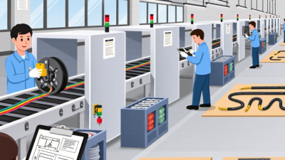
Why Is Wiring Harness Fabrication Important?
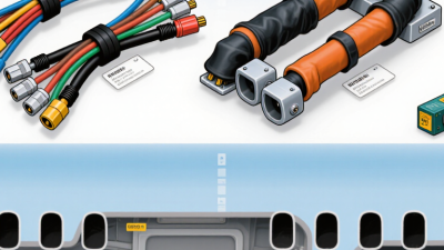
A wiring harness is more than a bundle of wires. It carries power and signals through vehicles, industrial machines, and electronic equipment, often in tight spaces exposed to vibration, heat, or moisture. Wiring harness fabrication turns a design into an organized assembly by measuring and cutting wires, stripping insulation, attaching terminals, and routing cables into protective sleeves. Each connection matters. A loose crimp or misplaced branch can interrupt a signal, complicate repairs, or cause a system to fail.
Careful fabrication helps make assemblies consistent, traceable, and easier to install. Technicians may use drawings, wire labels, fixtures, and specified crimping tools to keep each build aligned with its requirements. Continuity checks and visual inspections can catch issues before a harness reaches the final product. These steps are especially useful when an assembly contains many circuits or must fit a confined enclosure. Small details count.
The value is not only in preventing faults. A well-planned harness can simplify maintenance, reduce installation time, and make future changes easier to manage. Still, a neat-looking assembly is not automatically a reliable one. Material choice, connector compatibility, workmanship, and the conditions where the harness operates all deserve attention. Even good procedures have limits. Understanding why wiring harness fabrication matters begins with recognizing both its practical benefits and the checks needed to achieve them.
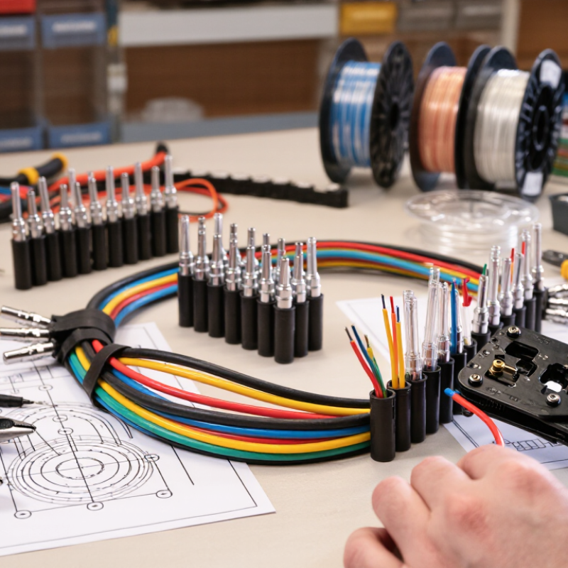
What Wiring Harness Fabrication Involves: Cutting, Stripping, Crimping, and Routing
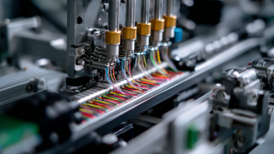
Wiring harness fabrication turns loose conductors into an organized, testable assembly. The work starts with measured cutting: a few millimeters of excess wire can complicate routing, while a short cut can strain a terminal. Stripping must expose enough copper for the contact, without nicking strands. Small errors travel.
Crimping joins the conductor and terminal through controlled pressure. Operators check the correct tooling, wire size, and crimp dimensions; a neat-looking joint is not proof of a sound connection. IPC/WHMA-A-620 provides industry acceptance criteria for cable and wire harness assemblies, including workmanship checks. Routing then places wires through clips, sleeves, and branches, preserving bend room and keeping abrasion points in view. It is easy to underestimate this step.
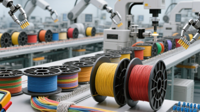
The scale makes consistent fabrication matter. Grand View Research’s 2023 automotive wiring harness market report estimated the market at USD 93.5 billion and projected a 5.7% compound annual growth rate from 2024 to 2030. That forecast does not measure defects, but it reflects how widely these assemblies are used. In practice, teams document cut lengths, inspect stripped ends, and verify crimps with gauges or pull tests. Still, inspection can miss a weak point hidden inside a dense bundle; careful routing and clear records reduce that risk.
How AWG, Current Load, and Voltage Ratings Guide Wire Selection
Wire selection starts with the electrical load, not the connector’s appearance. AWG numbers work in reverse: a lower number means a thicker conductor and usually less resistance. A 20 AWG lead may suit a small sensor, while a motor circuit may need heavier wire, depending on current and run length. Check expected operating and peak current, not only average draw. Peaks matter.
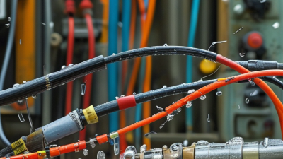
Current capacity also depends on heat. Bundled wires, warm enclosures, and insulation type can reduce a conductor’s safe ampacity. Longer runs add resistance and increase voltage drop. On a 12-volt circuit, even a modest drop may dim a lamp or slow a motor. Measure the full circuit path, including the return wire. Details are easy to miss.
The wire’s voltage rating must meet or exceed the system’s operating voltage and foreseeable transients. Its insulation must also suit the environment, such as heat, moisture, or abrasion near a metal panel. An AWG chart is a starting point, not a final answer; I would verify its assumptions against the wire data sheet and installation conditions. Extra margin takes space. A loose bundle may still overheat if airflow is poor.
Why Harnesses Must Support Both 12-V and 48-V Vehicle Systems
Why Is Wiring Harness Fabrication Important?
Why Harnesses Must Support Both 12-V and 48-V Vehicle Systems
Modern vehicles may use 12-volt circuits for lighting, control modules, and familiar accessories. A 48-volt system can serve higher-power loads, such as an electric compressor or mild-hybrid components. The two systems must work together without being treated as interchangeable. Voltage matters.
Harness fabrication helps define that boundary. Engineers select conductors, insulation, terminals, and connectors for each circuit’s expected load and environment. A 48-volt cable carrying substantial current may need a different gauge and routing plan than a small 12-volt signal wire. Poor choices can cause excess heat, voltage drop, or intermittent faults. Those problems may appear only during vibration or temperature changes.
Clear identification helps technicians avoid confusion during assembly and service. Different connector keys, labels, and documented pinouts can reduce the chance of connecting the wrong circuit. Physical separation also matters, especially near moving parts, sharp edges, or hot components. Test each finished harness for continuity, insulation integrity, and correct pin assignment. Then check it under realistic load conditions. A bench test is useful, but it cannot reproduce every vehicle condition. That gap deserves attention during design reviews. A neat harness is not automatically a reliable one. Proper fabrication depends on measured requirements, careful workmanship, and honest testing across both voltage systems.
How IPC/WHMA-A-620 Defines 3 Classes for Harness Workmanship
Why Is Wiring Harness Fabrication Important?
How IPC/WHMA-A-620 Defines 3 Classes for Harness Workmanship
A wiring harness may sit behind a panel, but its workmanship affects how reliably equipment operates. IPC/WHMA-A-620 sets acceptance criteria for cable and wire harness assemblies. It groups work into three classes according to the product’s intended use and performance needs. The standard guides inspection; it does not guarantee that a harness will never fail.
Class 1 covers general electronic products where function is the main requirement. Class 2 applies to dedicated-service products where continued performance matters, though brief interruptions may be acceptable. Class 3 is for high-performance equipment where reliable operation is critical, including demanding environments. Downtime may not be an option.
These classes shape how inspectors assess details such as crimp placement, exposed conductor strands, insulation support, and connector damage. Small defects can matter differently depending on the class. Not every harness needs Class 3. Choosing the class should reflect real operating conditions, not just a preference for stricter inspection. That decision can be awkward when a product’s risks are unclear, so teams should document their reasoning and confirm requirements with the customer. A class is a workmanship benchmark, not a substitute for sound design or careful testing.
How Continuity, Pull, and Insulation Tests Verify Finished Assemblies
Why Is Wiring Harness Fabrication Important?
A finished harness can look neat and still contain a hidden open circuit, weak crimp, or nicked insulation. That is why verification matters. Continuity testing checks that each conductor reaches its assigned pin and that unintended connections are absent. A low-resistance reading is useful, but it does not prove the assembly will perform safely under every load. IEC 60512 provides standardized methods for testing electrical connectors, while IPC/WHMA-A-620E defines workmanship acceptance criteria across three product classes. The required limits still depend on the product specification.
Pull testing checks whether a crimp can withstand the specified force without the wire slipping or separating. The correct force varies with wire size and terminal design; one universal threshold would be misleading. Insulation-resistance or dielectric tests can reveal leakage paths and damaged insulation between conductors. Test records should identify the assembly, test limits, measured results, and equipment calibration. Small details matter. A clean beep can hide a poor crimp.
Tips: Test before bundling hides connection points. Confirm the pin map, use limits from the approved drawing, and record failures before rework. Retest repaired assemblies. Some checks feel repetitive, but skipping one can leave uncertainty.