What Is the Best Wire Harness Assembly Process in 2026?

In 2026, the best wire harness assembly process is not a single machine or checklist. It is a controlled sequence that makes each connection repeatable, inspectable, and traceable. A harness may contain dozens of wire lengths, seals, terminals, and connector housings. One poorly seated crimp can interrupt the whole circuit. Small errors spread.

The process typically begins with verified drawings, approved materials, and clear work instructions. Operators cut and strip each wire to specified lengths, then crimp terminals with calibrated tooling. Crimp height, pull strength, and visual appearance need defined acceptance criteria. Connectors are assembled in the correct cavity positions, while branches are routed and secured against abrasion or excessive bending. Not glamorous. Essential. Continuity and high-voltage tests, where applicable, can help catch defects before shipment. Digital records also make it easier to trace materials, tooling, and test results back to a production lot.

Taiichi Ohno, a key figure in the Toyota Production System, is often credited with the principle, “Without standards, there can be no improvement.” That idea fits harness manufacturing: teams cannot reliably improve steps they have not defined or measured. Still, a documented process is not automatically a good one. A workbench can meet a procedure and remain awkward, slow, or prone to operator error. The strongest approach combines engineering controls, trained operators, in-process checks, and feedback from real production. This guide examines how those elements fit together, where automation helps, and which details deserve a second look.
What Is the Best Wire Harness Assembly Process in 2026?

Define Wire Harness Requirements and Create the Assembly Design

What Is the Best Wire Harness Assembly Process in 2026?

Define Wire Harness Requirements and Create the Assembly Design

A reliable wire harness begins with a clear account of its operating conditions. Record circuit function, voltage, current, temperature range, vibration exposure, and expected service life. Specify wire gauges, insulation types, connector positions, and acceptable cable lengths. A vague requirement can become a costly assembly error. Include pin assignments and connector views, since front and rear orientations are easy to confuse. I have seen small drawing assumptions cause larger rework later.

Turn those requirements into a controlled design package. Use a readable schematic, a connector table, and a harness layout with routing dimensions. Mark branch points, labels, protective sleeving, and minimum bend areas. Check that each wire reaches its terminal without tension, even around tight corners. Review the design against the installation space and maintenance needs. A prototype can reveal practical problems that the drawing misses; some dimensions may need revision, and that is useful feedback.

Tips: Verify pin numbers against the connector view before release. Build a sample, then check fit, continuity, and label readability. Keep revisions dated, and make sure production uses the current files. Don’t rely on memory.
Select Materials and Prepare Wires, Terminals, and Connectors

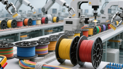
A reliable wire harness begins with materials suited to its electrical load, movement, and environment. Choose conductor size from current requirements and expected temperature rise, not habit. Match insulation to heat, moisture, abrasion, and nearby chemicals. Check the drawing against the actual parts before production. Small mismatches matter.

Before cutting, confirm wire color, gauge, and length against the approved work instructions. Measure from a consistent reference point, then cut cleanly without flattening the strands. Set the stripping tool to expose the specified conductor length while leaving insulation intact. Inspect each sample under good light. A nicked strand can weaken a crimp. Record material lots and setup changes so a later fault can be traced.

Select terminals that match both the wire range and connector cavity. Use the specified crimp tooling, and check crimp height or pull strength where the process requires it. Confirm that terminal locks engage and that seals sit evenly, without folds. A quick fit check helps catch errors early. Still, it is easy to rush this step when parts look familiar; appearance alone cannot confirm a sound electrical connection.

Cut, Strip, Crimp, and Assemble the Harness Components

What Is the Best Wire Harness Assembly Process in 2026?
Cut, Strip, Crimp, and Assemble the Harness Components

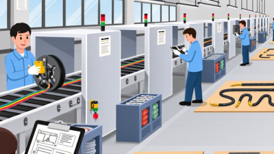
A reliable harness begins with the correct wire length. Use a cutting machine or a measured stop, then check the first pieces against the drawing. Even a small length error can pull a terminal sideways during assembly. Strip insulation to the specified length without nicking the copper strands. Inspect the exposed conductor under good lighting. Small defects are easy to miss.

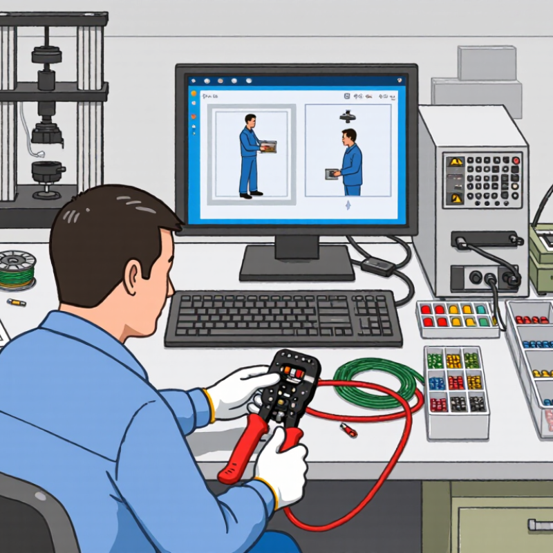
Crimping needs a matched wire, terminal, and applicator. Set the crimp height to the process specification, then verify samples with a pull test and visual inspection. IPC/WHMA-A-620 provides widely used workmanship criteria for cable and wire harness assemblies. It supports consistent checks, but it cannot replace sound tooling or operator judgment. A neat-looking crimp may still be weak.

During assembly, route wires through the board or fixture, fit seals and connectors, and secure branches without forcing bends. Check connector positions and continuity before final release. Keep measurements and inspection results with the job record; this makes repeated issues easier to trace. Training matters too. A 2024 study by Deloitte and the Manufacturing Institute estimates that U.S. manufacturing may need 3.8 million workers by 2033, with 1.9 million jobs potentially unfilled. That workforce pressure makes clear instructions valuable. They still need review: even a good checklist can miss a shop-floor problem.

What Is the Best Wire Harness Assembly Process in 2026? - Cut, Strip, Crimp, and Assemble the Harness Components
Process Stage Main Operation Key Setup and Process Controls In-Process Quality Checks Common Defects to Prevent
1. Review and prepare Confirm the latest wiring diagram, bill of materials, wire list, connector details, and assembly instructions before production. Verify wire type, conductor size, insulation, terminal compatibility, connector cavities, tooling, and revision status. Check material identification and condition; confirm that the work instructions and inspection criteria match the approved design. Wrong wire or terminal, outdated drawing, damaged materials, and incorrect connector configuration.
2. Measure and cut Feed and cut each wire to its specified finished length, accounting for the design’s routing and termination requirements. Set the cutting equipment using the approved length data. Keep wire lots separated and identify cut lengths to prevent mix-ups. Measure samples against the drawing or work instruction; inspect cut ends for clean, square cuts and visible damage. Incorrect length, nicked or crushed insulation, angled cuts, and mixed wire types.
3. Strip insulation Remove insulation to expose the conductor for termination without damaging or removing conductor strands. Set the stripping tool for the specified strip length and insulation type. Use the terminal or drawing requirements rather than a universal strip-length value. Check strip length, exposed conductor condition, strand count, and insulation edge. Inspect first pieces after setup and at the defined production frequency. Cut or missing strands, insulation left in the contact area, excessive exposed conductor, and insulation damage.
4. Crimp terminals Attach the specified terminal to the stripped conductor using the correct applicator or crimp tool. Match the terminal, wire size, applicator, and tooling setup. Control crimp height and other settings to the terminal specification; use force monitoring where required. Inspect terminal position, conductor and insulation support, bellmouth, and visible strand placement. Measure crimp height and perform pull testing when required by the control plan. Loose or incomplete crimp, over-crimping, misplaced conductor, folded strands, damaged terminal, and insulation trapped in the conductor crimp.
5. Insert contacts Install crimped contacts into the designated connector cavities and fit seals, locks, or retainers where specified. Follow the cavity map and insertion direction. Use the specified insertion and extraction tools; do not force a contact into a mismatched cavity. Verify wire color and cavity position, confirm contact retention with the specified check, and inspect secondary locks and seals. Wrong cavity, backed-out contact, bent contact, missing seal, and incomplete secondary-lock engagement.
6. Route and assemble Arrange wires and branches on an assembly board or fixture, then add specified sleeves, conduit, clips, labels, and protective materials. Follow the harness layout, branch points, orientation, and bend guidance in the design. Keep wires free from unnecessary tension, twisting, and sharp-edge contact. Compare the assembly with the layout; check branch lengths, component locations, routing, labels, and required clearances. Incorrect branch position, crossed or twisted wires, missing components, loose protection, and routing that strains terminals.
7. Secure and finish Apply specified ties, clips, wraps, seals, or other retention features and complete connector and protective-cover assembly. Use the specified materials and placement. Avoid over-tightening ties or applying heat beyond the material and process instructions. Check retention, coverage, connector condition, label readability, and workmanship against the approved acceptance criteria. Pinched insulation, loose retention, blocked connector features, incorrect label placement, and heat-damaged materials.
8. Test and release Perform the electrical and visual tests required by the product design and inspection plan before packaging. Use a suitable test fixture and the approved test program. Define continuity, short-circuit, and any additional test limits from the product requirements. Record required test results; verify connector pin mapping, circuit continuity, isolation where specified, and final appearance. Open circuits, crossed circuits, shorts, intermittent connections, and shipment of an unverified or incorrectly identified harness.

Process settings and acceptance limits are product-specific. Use the approved drawing, terminal and wire specifications, work instructions, and quality control plan for the harness being built.

Route and Secure Wires According to the Assembly Layout

What Is the Best Wire Harness Assembly Process in 2026?

A reliable wire harness assembly process starts with the layout, not a bundle of loose wires. Before routing, confirm connector positions, branch lengths, clip locations, and service loops against the current drawing. Mark the board clearly. Keep labels readable and wire orientation consistent. A layout that looks tidy on screen may still create awkward bends at the bench.

Route conductors along the specified paths, keeping branches separate until their paths meet. Use approved clips, ties, or combs at planned intervals without crushing insulation or pulling wires taut. Follow the bend-radius guidance for each wire and component. Leave connectors enough slack for mating and inspection, but avoid loops that could snag. Small details matter. Keep wires clear of sharp edges, moving parts, and hot surfaces.

Secure the harness progressively, checking each branch before adding the next restraint. This makes misrouted wires easier to spot and reduces rework. Compare the finished assembly with the board and drawing, then verify connector orientation, labels, and restraint positions. Gently lift the harness: branches should hold their route without strain. Not every fixture reflects real handling perfectly. Review tight bends and crowded areas with the assembly team; those spots can reveal problems a neat-looking board hides.

Inspect, Test, and Document the Finished Wire Harness

What Is the Best Wire Harness Assembly Process in 2026?

A dependable process ends with careful inspection, testing, and clear records. Check each finished harness against its drawing and bill of materials. Look for damaged insulation, loose terminals, incorrect wire colors, and connectors seated at the right depth. Small details matter. Use good lighting and verify labels are readable before packing. Even experienced teams can miss a pin pushed slightly backward, so inspect connector faces from more than one angle.

Tips: Use a checklist for each harness type. Confirm test equipment is within its calibration interval, and record the operator, date, and result. Do not guess. If a reading seems unusual, pause and repeat the test.

Electrical testing should match the design requirements. Continuity checks can reveal open or misrouted circuits; insulation or resistance checks may help identify other defects when required. Test every specified circuit, not just a convenient sample. Document the test method, limits, actual results, and any rework. Keep records tied to a unique harness or production lot, so a later question can be traced to the correct unit. A neat form cannot fix a weak inspection, but a complete record makes the process easier to review and improve.

What Is the Best Wire Harness Assembly Process in 2026?

Inspect, Test, and Document the Finished Wire Harness

This chart shows a recommended release target, not measured industry results: complete and record every check required by the approved drawing and customer specification. Insulation testing should be performed when specified.